A journey of a thousand miles…
- brian
- Oct 30, 2012
- 2 min read
By Alexander Fund

The design of the foot began with the desire to improve upon the walking motion that a 3 Mobot configuration with a 4×4 snap connector could do. In this new configuration, the feet snap connectors would shift the center of mass from side to side instead of using a third Mobot.
To determine an approximate angle for the feet, the center of mass for each Mobot was first assumed to be in the center of each Mobot and the mass influence of the snap connector was ignored. In the 2 Mobot configuration, the center of mass would then be located midway up the Mobots and directly in between them. With this point known, the angle at which the configuration could be tilted to transfer the center of mass directly over the inner edge of the Mobot was determined to be approximately 11.25 degrees. When visually tested with a Mobot configuration, the angle felt too large and was reduced based on inspection. The configuration was propped up at varying angles until it balanced which resulted in elevating the inner foot approximately 0.2 inches or tilting the configuration at an angle of approximately 7.59 degrees.
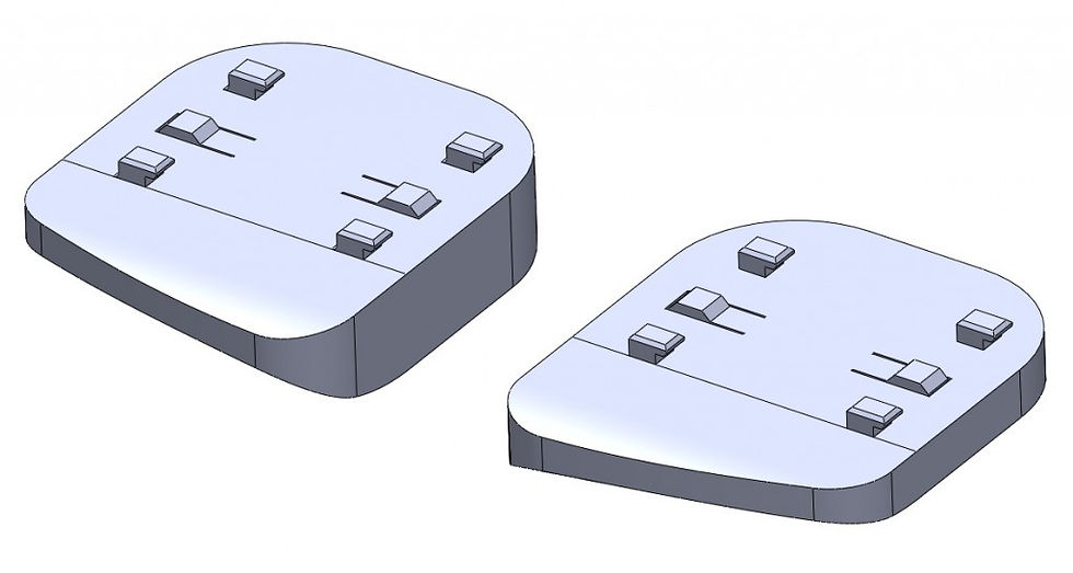
To test this foot angle, simple feet were prototyped. Upon testing, the Mobot configuration could balance on each foot, and a walking program was developed. However, the simple feet did not convey a smooth walking motion as the feet ended with sharp edges.
To generate a smooth walking motion, a curved “toe” was added to the front of the foot. The foot curve was designed to match the simple foot walking motion such that the Mobot configuration would rock forward instead of going through a programmed motion. Fillets and a spline curve cut were then added to make the foot look more like a foot.

Experimental ribbing


Comments